This circuit utilizes a photo resistor and a RGB LED. The photo resistor is used to determine how much surrounding light is present, which in turn controls the notes played on S4A by a violin. As less light is present, the notes, which are pizzicato (plucked) violin notes, are lower, and when more light is present, the notes are higher. The RGB LED changes between red, green, cyan, and yellow based on the notes as well.
The following diagram shows the setup of the circuit:

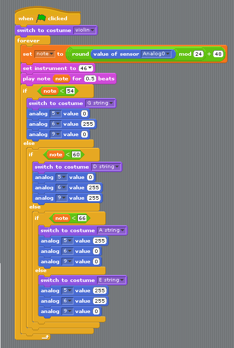
Our S4A code for the circuit is shown below. In addition to the photo resistor controlling the notes played by the S4A violin, as well as the RGB LED, we set up a visual display of a violin that is altered by the photo resistor. When certain notes are played, the different strings of the violin (E, A, D, and G) are lit up in, each with a different color. These colors match the colors of the LED when the notes are played (red, green, cyan, and yellow) so that when matching the physical and virtual setups, it is easier to see the correspondence between them.
Watch the following video to see how interacting with the photo resistor affects the notes played by the S4A violin, the virtual violin strings, and the color of the RGB LED:
[youtube http://www.youtube.com/watch?v=1wUAKCzvP6s&feature=youtu.be&w=560&h=315]